C o m m o n c o n n e c t o r w i r i n g
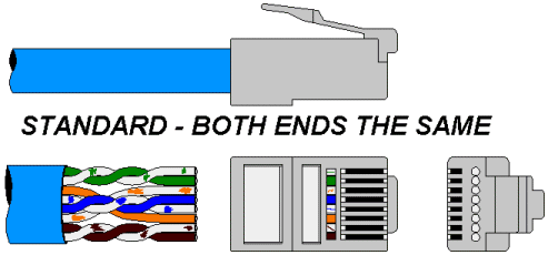
Category 5 UTP Patch Cable Standard EIA/TIA-568A:
For a standard Patch cable, for use between a Network Interface Card (NIC) and a Hub port, both ends are wired identically. Arrange the wires into the positions (colours) shown, maintaining the twist rate as close as possible to the connector but not past the wire clamping mechanism. Use a good quality connector and a good quality crimp tool.
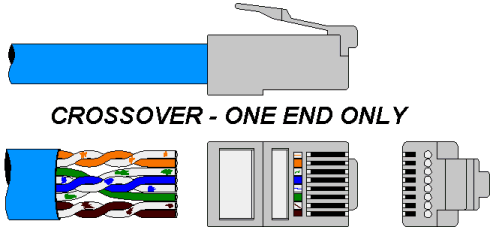
Category 5 UTP Patch Cable CROSSOVER EIA/TIA-568A:
For a CROSSOVER Patch cable, for use between a Network Interface Card (NIC) and another NIC each end is wired differently. One end is wired as for a standard Patch Cable and the other end is wired as shown above. Arrange the wires into the positions (colours) shown, maintaining the twist rate as close as possible to the connector but not past the wire clamping mechanism. Use a good quality connector and a good quality crimp tool. ALWAYS clearly mark as a crossover cable at BOTH ends.
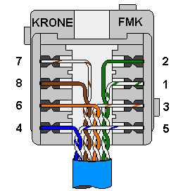
Category 5 UTP Wallplate (Krone FMK) EIA/TIA-568A:
For normal, HUB to NIC "Wall" or "Patch Panel" cabling, each end of the cabling should be wired the same as above and standard patch cables should be used at each end. EIA/TIA 568B allows for a crossover to be wired into the wall cabling but we do not recommend this approach as it leads to confusion, particularly when normal and crossover patch cables are used. Arrange the wires into the positions (colours) shown, maintaining the twist rate as close as possible to the termination (max. 13mm untwisted). Use the correct Krone termination tool.
Make sure FMK sockets are installed with the RJ contacts placed to the top, in the orientation shown above.
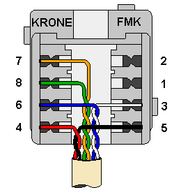
ISDN Wallplate (Krone FMK):
Arrange the wires into the positions (colours) shown, maintaining the twist rate as close as possible to the termination (max. 13mm untwisted). Use the correct Krone termination tool.
Make sure FMK sockets are installed with the RJ contacts placed to the top, in the orientation shown above.